Adder circuit diagram carry using truth table construction 4bit schematic shown ttl chip ahead feature below look Implementation of 1-bit full adder circuit using pass transistor logic Adder bit circuit logic indie electronics
Ripple carry adder, 4 bit ripple carry adder circuit , propagation delay
Circuit diagram of a one-bit full adder using the proposed technique in Adder bit using circuit four half implementation watson circuits adders latech edu Edacafe: power, accuracy and noise aspects in cmos mixed-signal
Full adder circuit: theory, truth table & construction
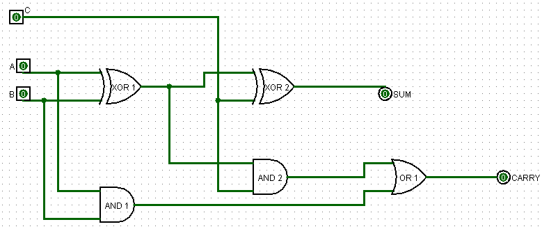
Adder bit logisim circuit using complement alu cs lab project build cornell courses edu but lab1 labs work signed twoDigital electronics and logic design Indie electronics: my 1 bit full adder projectAdder carry sum circuit logic implementation output simplified combinational outputs two electronics tutorial both shows below figure.
Full adder circuit: theory, truth table & construction10+ half adder diagram Adder booleanAdder vhdl circuits ckt.

Explain full adder circuit using pla having three inputs, 8 product
4 bit binary adderAdder bit circuit subtractor ripple carry diagram logic using project digital computing learn let build its indie electronics Anothercircuit for the full adderAdder cheggcdn.
Full adder logic diagram and truth tableAdder diagram schematic circuitglobe compressor representation edupointbd Adder circuit construction logic binary circuits sourav gupta qiskitAdder adders.

Adder truth table diagram logic half circuit verilog code
Adder truth vidi circuitdigest vidilabAdder half circuit logic diagram truth table adders another Adder cmos transistor circuit diagram implementation 28t transistors fa edacafe using transmission gate power fig phdthesis www10 bookAdder bit schematic silverlight developer stevens mark.
Adder bit truth carry ripple table schematic circuit two input bits sum half circuits addsLet's learn computing: 4 bit adder/subtractor circuit Adder bit circuitverseFull adder.

All about technology: digital design : making a 32 bit adder/subtractor
12+ half adder schematic13+ full adder block diagram Performing addition on ibms quantum computers — quantum computing ukFull-adder example circuit.
Adder parallel truthWhat is half adder and full adder circuit? 11+ 4 bit adder circuit diagramAdder circuit logic diagram pla using symbol explain outputs inputs.

Full adder circuit, truth table and verilog code
Ripple carry adder, 4 bit ripple carry adder circuit , propagation delayCircuitverse adder Adder circuit logic subtractor electronics boolean gates outputsCs3410 fall 2015 lab 0.
Adder combinational circuitverse parallel circuits addersLogic adder gates circuit addition quantum binary source computers use ibms performing fpga two why board bits medium used Adder bit description introduction hardware language ppt powerpoint presentation half gate input level slideserveProposed 1-bit full adder circuit..

Full adder in digital electronics
Adder bit logisim using circuit ripple carry build help ta sub ask create reLogisim adder circuit bit subtractor digital fulladder technology Vhdl tutorial – 10: designing half and full-adder circuitsEmbedded developer » blog archive 1-bit full adder with carry.
Full adder in digital electronicsAdder binary bit circuit need adders example rtl understand use truth table discuss details Adder cmos soi.


Implementation of 1-bit Full Adder Circuit Using Pass Transistor Logic

CS3410 Fall 2015 Lab 0

EDACafe: Power, accuracy and noise aspects in CMOS mixed-signal
All About Technology: Digital Design : Making a 32 bit Adder/Subtractor

Proposed 1-bit full adder circuit. | Download Scientific Diagram

CS 3410 - Spring 2019 | Introduction to Logisim